

Three types of single, three and seven-strand conductors in earth and connection applications, lightning arrester and clean earth (clean earth)

Investigating the role of conductor in the conduction rate of earth conductor
Today in the world in the industry of earth system and lightning arrester (protection against lightning), various types of single and multi-strand conductors are used. We pay the inductance and reactance of the self-conductor.
The purpose is to investigate the induced reactance for applications of lightning conductor, conductor and ground conductor or earth well wire.
Behnam Asan Kimia Company, the creator of new methods of earthing and lightning protection and main and additional connection with various horizontal and vertical electrodes of earth and earth conductors and producing all kinds of conductors required in the earth industry and connection with the approach of improving quality and economy Therefore, one of the best types of conductors is acceptable conductors of hot-dip galvanized steel wire for the ground system (either as a connector or as an electrode inside the well or next to an integrated percussion rod, an exclusive product of Behnam Asan Company. Alchemy) and bondage and lightning arresters
.
Computational method of inductance correlation
In this article, Maxwell electromagnetic analysis software, which is used in magnetic analysis of electric machines, has been used and its results are presented in the form of figures and diagrams
n choosing a conductor, and if we need flexibility in our project location, we should definitely use multi-strand conductors that are from 3, 5, 7 and 19 strands. And the single string conductor will not be respons
It is important to mention that the conditions where the wire or conductor is used is the most important factor in choosing a conductor, and if we need flexibility in our project location, we should definitely use multi-strand conductors that are from 3, 5, 7 and 19 strands. And the single string conductor will not be responsible.
In practical applications, woven (stranded) conductors are mostly used. This is due to the softness, flexibility and ease of installation.
But the use of single wire conductor (round wire) also has its place and is suitable in places where it can be used.
Simulation of 1, 3 and 7-strand conductors if they are wrapped in 5 loops.
Using the ground electrode as a ring, in addition to the mentioned advantages, also has disadvantages that the biggest and most important drawback of this method is to
increase the inductance of the ring electrode installed on the rod electrode.
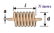
The inductance relationship of a ring for a ring as shown in Figure 1 is as follows:
If we ignore the radius of the loop wire against the outer diameter of the loop, this relationship is approximately as follows:
In the above relations:
N number of round loops
0. Magnetic permeability coefficient of air
µr The magnetic permeability coefficient of the location of the ring
d The outer diameter of the ring
a radius of the loop wire
l The length of the ring
L ring inductance
Are.
When a sine wave is applied to the electrode, a sine current will pass through the electrode, which is used to check switching and lightning conditions, as well as high frequency sources such as inverters, chargers and servers. In this case, the reactance loop against the current passing shows that it is equal.
In this regard, X1 is the reactance and f is the frequency of the wave applied to the electrode.
According to Equation 3, the amount of reactance at high frequencies such as lightning wave frequency is very high and in fact this value is not acceptable according to the standards, but at 50 Hz city frequency and using methods to reduce inductance, the amount of reactance can be reduced. And reaching an acceptable value.
The inductance values in all these reduction methods were calculated based on Equation 1 and simulated in Ansys Maxwell software and the results were analyzed by Equation.
The primary operating ground electrode ring has the following specifications:
d = 40 mm
a = 5 mm
N = 200
l = 14
To present the simulations, it is important to pay attention to the following points:
1- Since the environment is the location of the soil electrode and the magnetic property of the soil is almost equal to air, in the simulations we have considered the external environment of the electro-ring as air 1, based on which the magnetic permeability coefficient of the soil is equal to one.
2- Due to the complexity of transient simulations in Maxwell software for 200 rounds, these simulations have been performed for 5 rounds of the loop. The following is:
Equation 4 1600 ×Inductance (5 rounds) = Inductance (200 rounds)
3- The analysis was performed in transient mode and to simulate the current wave connected to the earth electrode, a current source with a range of 1 kA and a frequency of 50 Hz was used. The ohmic resistance of the ring is also considered to be 0.5 ohms.
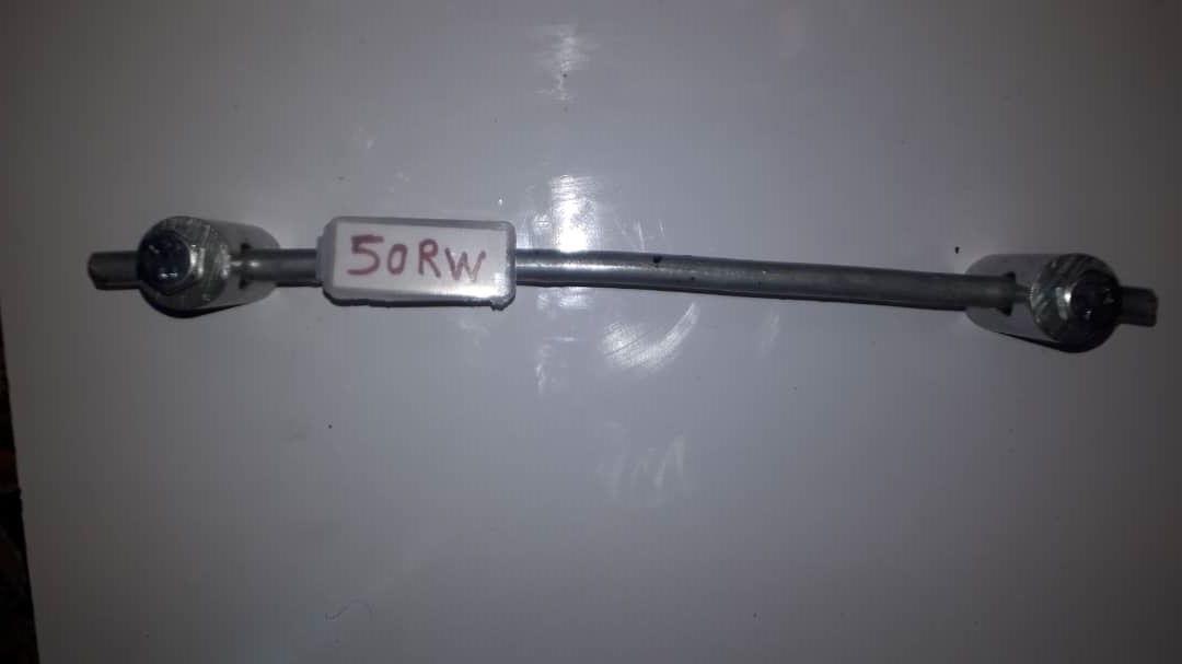
1- Simulation of steel wire or conductor in the form of a loop (coil) with 7-strand texture with a diameter of 3 mm per strand and an approximate cross-sectional area of 7.5 mm and with a total conductor diameter of 9 mm and a total cross-sectional area of 50 mm2 circular cross-section O full):
4 A coil with the following general specifications and equivalent circuit is used:
d = 40 mm
a = 5 mm
N = 5
l = 150 mm
- Simulation of steel wire or conductor in the form of a loop (coil) with 7-strand texture with a diameter of 3 mm per strand and an approximate cross-sectional area of 7.5 mm and with a total conductor diameter of 9 mm and a total cross-sectional area of 50 mm2 circular cross-section O full)
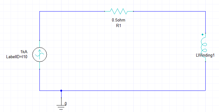
We model each coil with a series of electrical resistors in series with an inductor inductance whose circuit is shown in